When an engineer sends us a filter requirement, the conversation rarely starts with the quality factor. It starts with the center frequency, the bandwidth, the rejection targets. But within a few emails, the Q factor ends up deciding most of the design, because it sets how sharply a filter can separate the passband from everything around it, and how much signal you lose getting through. This article explains what the quality factor of a filter actually measures, how to calculate it, and how it plays out in real RF projects, using examples from the cavity and band pass filters we build at Yun Micro.
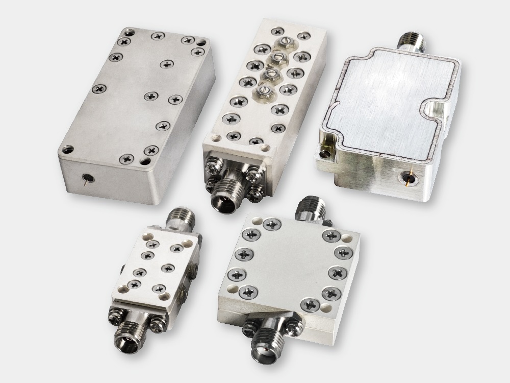
The quality factor (Q factor) of a filter is a parameter used to measure its frequency selectivity and energy loss. A higher Q factor generally indicates lower internal resonator losses and better frequency selectivity, allowing the filter to select the target frequency range more precisely. The commonly used formula is:
Q = f0 / BW
where f0 is the center frequency and BW is the 3 dB bandwidth. In plain terms, Q compares two things that both matter to the system designer: how high the filter operates, and how wide a window it opens. The same Q value can describe a narrow filter at a low frequency or a wide filter at a high frequency, which is why two filters with identical Q can behave very differently in a radio chain.
For a bandpass filter, a higher Q factor usually means a narrower passband. That is not a defect — it is the trade the design is built around. Selectivity and bandwidth pull in opposite directions, and every real filter finds a point between them.
Numbers make this easier to see. Take an RF bandpass filter from Yun Micro with a center frequency of 2.4 GHz and a 3 dB bandwidth of 100 MHz. The loaded quality factor works out to 24 (2400 / 100). If the same filter is redesigned with the bandwidth tightened to 50 MHz while keeping the center frequency, the Q factor rises to 48 — a narrower, more selective frequency response, but also a filter that demands more from its resonators.
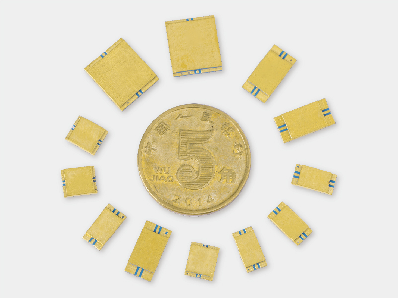
It is worth pausing on what physically changed between those two designs. Halving the bandwidth at the same center frequency means the resonators must store energy longer before releasing it to the output. Stored energy that lingers is exactly what unloaded losses eat into, which is why narrowband filters are where resonator quality stops being a datasheet detail and becomes the main design constraint.
In practical applications, the Q factor directly affects a filter's insertion loss and out-of-band rejection. In the 5G RF front-end modules used in smartphones, for example, narrowband filters require high-Q resonators to reduce passband losses and improve adjacent-channel interference suppression. Every dB saved in the passband is a dB the power amplifier does not have to fight for, and steep rejection skirts are what keep a neighbouring band from leaking into the receiver.
That said, a higher Q factor is not automatically better. High-Q designs are more sensitive to tolerance and temperature drift, take up more volume for the same connector style, and usually cost more to machine and tune. A wide-bandwidth application — a diplexer feeding two arms of a multi-band system, for instance — may be better served by a moderate-Q design with flatter passband ripple. The right target is the Q your system needs, balanced against bandwidth, insertion loss and overall performance, not the largest number on the datasheet.
The achievable Q is ultimately decided by the resonator inside the filter. Air-filled cavity filters sit at the top of the range: the current flows on polished metal walls rather than through lossy dielectric, so unloaded Q values reach into the thousands, which is why cavity construction dominates high-power and high-selectivity work from base stations up to satellite links.
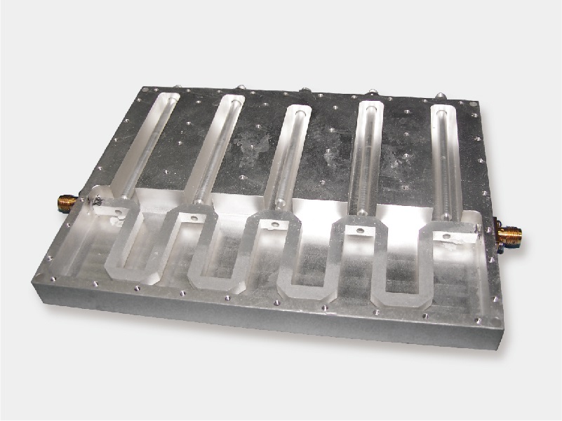
The picture above shows what that looks like in practice — the machined resonator posts inside a cavity body. Their surface finish, spacing and tuning screws are where the Q is won or lost, and where our production effort goes. When a design needs a compact footprint instead, dielectric resonator filters offer Q values between cavity and planar technologies, while LTCC filters and thin-film designs trade some Q for a size reduction of an order of magnitude. Knowing which ceiling each technology has lets you shortlist the right construction before the first simulation run.
In project terms, the choice usually comes down to three questions. First, how close is the nearest interfering signal? Adjacent-channel and image rejection requirements push Q upward. Second, how much insertion loss can the link budget absorb? A high-Q narrowband filter with a well-designed passband often beats a cheap wide filter once system noise figure is counted. Third, how much space and power handling does the assembly allow? Where the answer points to a high-Q requirement beyond a standard catalogue part, our customized cavity filter service covers the tuning and temperature-stability work that high-Q designs need.
Beyond band pass designs, the same Q thinking applies across the whole filter family: our low pass filter and high pass filter lines use the same resonator platforms, and where a specific band must be blocked rather than passed, cavity bandreject filters apply high-Q resonators to place a deep, narrow notch exactly where the interference lives.
What primarily limits the unloaded Q factor of a microwave filter?
The unloaded Q is predominantly limited by conductor losses—specifically the surface resistance caused by the skin effect at high frequencies—and dielectric losses. Employing highly conductive surface platings, such as silver, and maximizing the volume-to-surface-area ratio of the resonant cavity are standard engineering methods to improve the unloaded Q.
How does the Q factor directly impact insertion loss?
Insertion loss is inversely related to the ratio of unloaded Q (Qu) to loaded Q (Ql). To achieve a low insertion loss in a narrowband application (which inherently requires a high Ql), the physical resonator must possess a significantly higher Qu. If Qu is not sufficiently large compared to Ql, the internal energy dissipation will cause severe signal attenuation within the passband.
Why not always use the highest possible Q factor for every design?
While a high Q provides excellent frequency rejection and low loss, it also leads to a much narrower bandwidth, larger physical cavity dimensions, and heightened sensitivity to manufacturing tolerances and environmental temperature variations. Furthermore, extremely high Q circuits can cause group delay distortion, which negatively affects high-speed digital data transmission. Therefore, the Q factor must be purposefully optimized for the specific system requirements.
Yun Micro is a professional manufacturer of RF passive components, offering cavity filters up to 40 GHz, including band pass, low pass, high pass and band stop types. If you are weighing Q factor against bandwidth and insertion loss for a specific project, send us the centre frequency, bandwidth and rejection targets — our engineers will come back with a feasibility review and a proposed construction.
Welcome to contact us: liyong@blmicrowave.com


habla a : Xisan Road, Mechanical and Electrical Industrial Park, No.767 Yulan Road, Hefei,Anhui.
teléfono : +86-18855146875
Email : liyong@blmicrowave.com


escanealo


